Engineering release guide
PCB manufacturing files checklist.Verify the package, not just the design.
A PCB fabrication package normally needs layer artwork, drill data, a board outline, stackup, and fabrication notes. PCB assembly adds an exact BOM, pick-and-place data, assembly drawings, variant state, and any test or programming instructions.
- Fabrication data
- Assembly data
- Independent CAM review
- Revision-bound approval
Prepared by Struct contributors · Updated August 4, 2026
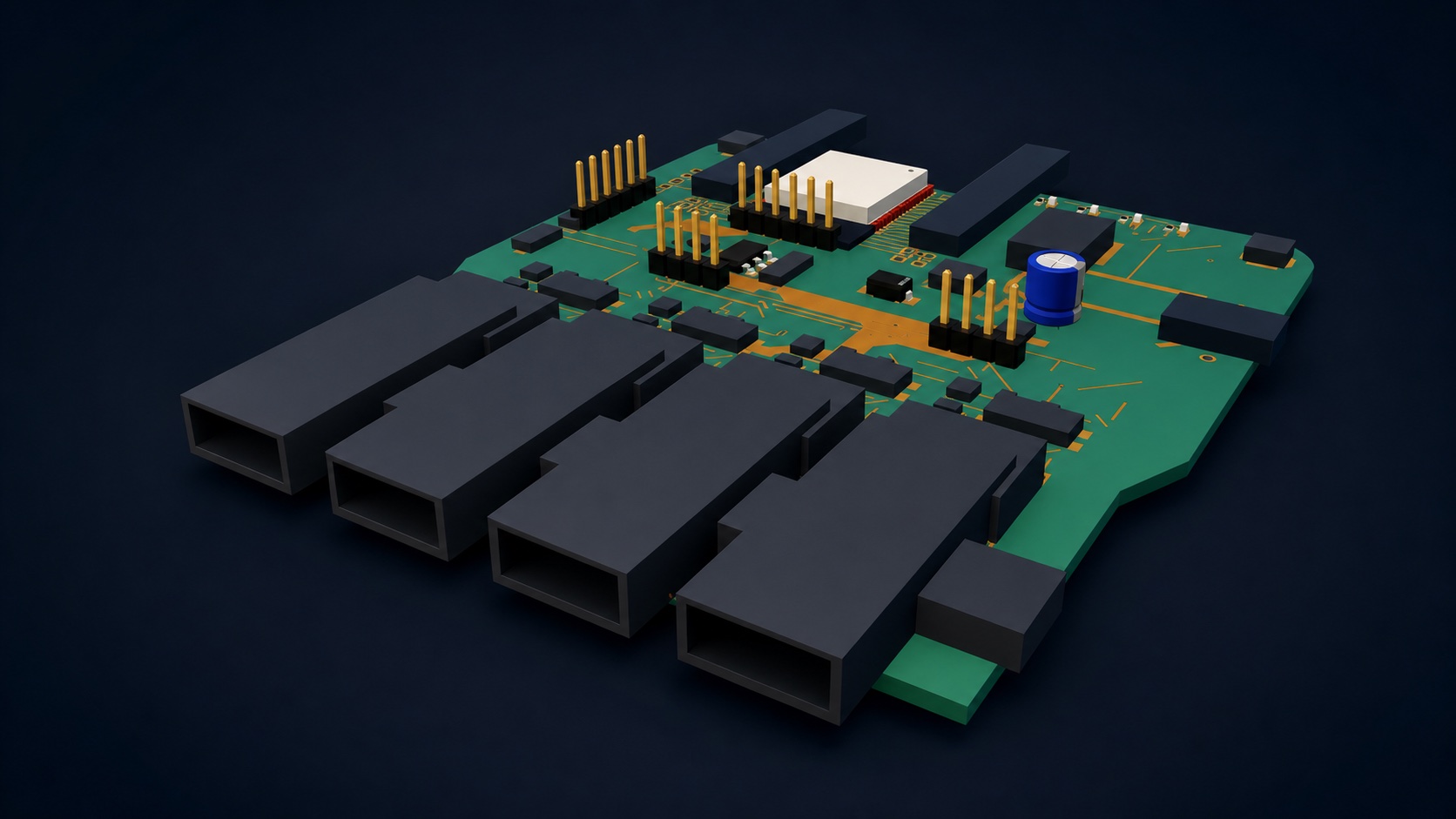
Inspecting the board model is useful, but only the exported CAM, drill, BOM, placement, and release files define the handoff package.
Start with the recipient
Separate fabrication, assembly, and source packages.
A board fabricator images and drills the bare PCB. An assembler places and joins components. A future engineer needs the editable design source. Keep those purposes explicit instead of sending one unexplained folder.
Fabrication package
Defines the bare board: copper, masks, legend, outline, drills, routes, stackup, materials, finish, tolerances, and fabrication notes.
Assembly package
Defines the fitted product: exact component identities, quantities, placements, orientation, side, variants, drawings, process notes, and test intent.
Editable-source package
Preserves the authoritative schematic, PCB, libraries, constraints, specifications, and revision context needed to inspect or revise the design.
Bare-board fabrication files
Give CAM every physical layer and hole definition.
Gerber is the common image-transfer format for copper, mask, legend, and related PCB layers. Ucamco maintains the official Gerber format documentation. Your chosen fabricator's current requirements remain controlling.
Confirm alignment, polarity, apertures, slots, and the final board perimeter.
- Copper
- All layers
- Drill
- PTH + NPTH
- Outline
- One closed profile
- □Copper artworkOne correctly identified file for every signal or plane layer in the approved stackup.
- □Solder mask, paste, and legendTop and bottom files as applicable, with apertures, polarity, text, and component markings independently inspected.
- □Outline and routed featuresOne unambiguous closed board perimeter plus cutouts, slots, scoring, tabs, or routed openings.
- □Plated and non-plated drillsHole coordinates, finished-size intent, tool definitions, slots, and layer spans reconciled to pads and the fabrication drawing.
- □Stackup and fabrication notesLayer order, material, thickness, copper weight, finish, mask and legend colors, controlled impedance, tolerances, quantity, and revision.
PCB assembly files
Make part identity, placement, and orientation agree.
Gerbers do not tell an assembler which exact orderable part to fit or how a variant changes. Reconcile every fitted reference across the BOM, placement file, assembly drawing, and board markings.
Exact bill of materials
Include reference designators, quantity, value, exact manufacturer and manufacturer part number, approved alternates, footprint or package, fitted/DNP state, and procurement notes.
Pick-and-place or centroid file
Confirm reference, X/Y coordinates, units, origin, rotation convention, top/bottom side, fitted state, and the treatment of bottom-side coordinates and angles.
Assembly drawings and notes
Show reference designators, board side, pin 1, polarity, connector orientation, mechanical or hand-placed parts, special process instructions, and variant identity.
Test and programming inputs
Attach approved firmware, programming procedure, test-point map, test limits, fixtures, acceptance criteria, serialization, labels, and traceability requirements when applicable.
Pre-release checklist
Approve the exact bytes you intend to send.
A clean editor view, generated ZIP, or supplier upload preview is not a release. Tie approval to one named revision, record the checks that ran against it, and preserve the exact package contents and fingerprints.
- □Revision identity is consistentBoard, schematic, BOM, placement file, drawings, notes, filenames, and order form name the same controlled revision and variant.
- □ERC and DRC are currentChecks ran against the released design fingerprint; resolved, waived, and blocking findings remain traceable to source objects.
- □CAM was reopened independentlyEvery copper, mask, legend, outline, drill, and routed feature was inspected from the exported files rather than only inside the design editor. Ucamco provides a reference Gerber viewer.
- □BOM and placement reconcileEvery fitted physical reference appears with one exact identity and placement; DNP, alternate, non-BOM, and mechanical items are classified explicitly.
- □Supplier DFM is completeThe selected fabricator and assembler reviewed the actual stackup, capabilities, constraints, files, substitutions, quantities, and test expectations.
- □Package integrity is recordedFabrication, assembly, and editable-source manifests list the exact filenames, byte sizes, hashes, author, review state, and named approval.
PCB manufacturing file questions
Common handoff questions, answered directly.
Ask the selected manufacturer for its current file, naming, origin, layer, panelization, assembly, and test requirements before freezing the package.
Which files are needed to manufacture a PCB?+
A bare-board fabrication package normally needs Gerber or another accepted CAM dataset for every required layer, plated and non-plated drill data, the board outline, stackup, and fabrication notes. An assembled-board package also needs an exact BOM, pick-and-place data, assembly drawings, and any required test or programming instructions.
Are Gerber files enough for PCB assembly?+
No. Gerbers describe board images and fabrication layers. Assembly also requires component identity and quantity in the BOM, placement coordinates and rotations, side and orientation evidence, DNP or variant state, and any special assembly or test instructions.
Should manufacturing files be checked outside the PCB tool?+
Yes. Reopen the exact exported CAM files in an independent viewer, verify drills and layer alignment, reconcile BOM and placement data, and complete the selected manufacturer's DFM review before approving a release.